Products
Image and Data Processing
3D photogrammetric system Kuraves-MD
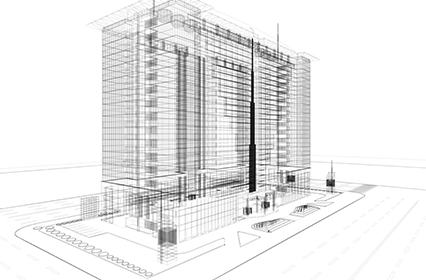
A photogrammetric system for obtaining data of various natural objects and structures by outputting 3D position coordinates (X, Y, Z) of the object from more than one image (photo) taken with a digital camera.
The measurement results can be used for calculating the length, area and volume of the object, creating sectional views, and calculating angles, as well as converting them into CAD data for synthesizing and creating additional drawings.
Features
Dedicated camera unnecessary for measurement
Any commercially available camera can be used. Allows anyone to take measurements swiftly.
Measurement points unnecessary
If scales or length data of the object are inputted into a captured image, scaled 3D data can be created. Multiple matching points can be automatically plotted with the automatic matching function.
Allows soil volume measurement
Soil volume in a 3D generated shape can be measured with the use of a plotting tool.
Visual representation
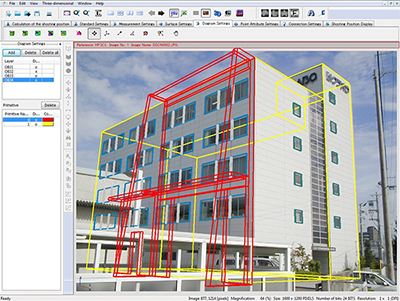
Improved 3D simulation function allows visual representation of measurement results created from captured images. Persuasive materials and reports can be created.
Basic operation
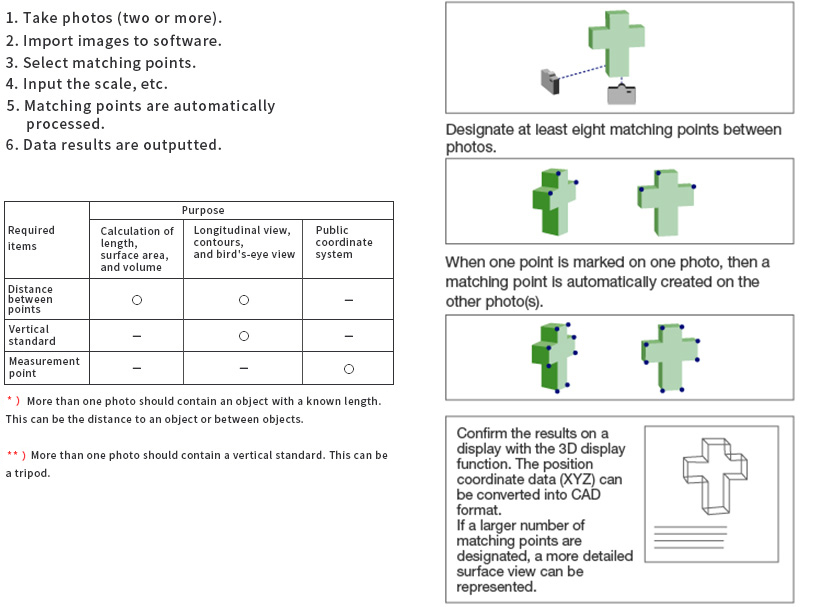
Operation example

Functions
Correction function for camera lens distortion (camera calibration tool)
When using a commercially available digital camera, it is necessary to correct the lens distortion of each camera. Kuraves is equipped with a camera lens distortion correction tool for easily obtaining the corrected value.
Automatic processing of matching points
Enhanced function for automatically matching the necessary lines and grid planes. Since the matching points are automatically created with use of the pattern matching method, 3D measurements of several thousand points can be carried out instantaneously. This is one of the most automated functions in this system, becoming more sophisticated with the addition of various auxiliary processing functions.
Measurement point registration function
Allows the entry and utilization of points measured by other devices such as a surveying instrument. The points can be converted to the public coordinate system or fixed in order to measure displacement.
Measurement point registration function
Allows the entry and utilization of points measured by other devices such as a surveying instrument. The points can be converted to the public coordinate system or fixed in order to measure displacement.
Simple length measurement function, angle measurement functionMeasurement results of slant distance, depth distance, and vertical distance can be displayed on any window by designating two points with a mouse. Angle coordinate points can be measured from any photo or any window on the XY or XZ planes, so it is suitable for measurement between objects.
3D display function
Analyzed data can be viewed freely by rotating, scaling down, or changing a view point with the 3D display function. This function is useful for confirming shapes (presentation) and detecting input errors of matching points. Textures can be pasted.
Area and distance calculation function
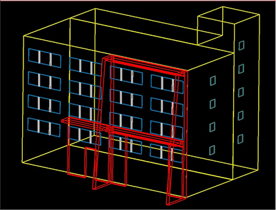
Area and distance can be calculated and outputted as a list instantly by point touching with a mouse or using the installed function that automatically creates a triangular network.
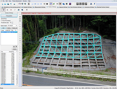
Ortho-image 3D display function
An object having a triangular network created with the area calculation function can freely be viewed by rotating, scaling down, or changing the view point with the 3D display function. This function allows the confirmation of shapes (presentation), detection of input errors of matching points, and outputting ortho-images to GIS, etc. It can also import external data such as contours (DXF) to simultaneously display / output with photos.
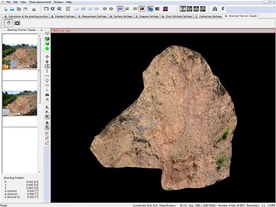
Contour and longitudinal / sectional view creating function (plotting tool)
A contour map can be created instantly by setting the height and output range of contours. A longitudinal / sectional view can easily be created by just drawing lines on the map.
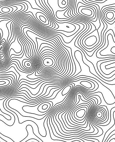
Volume calculation (soil volume calculation) function (plotting tool)
Volume can be calculated by specifying a place for removal, such as an amount of soil or the volume of a hole. By inputting a plan drawing or previous condition, the earth fill / cut volume can be confirmed and determined by comparing it with current conditions with on-site earth fill / cut simulation.

Multiple image connection function
A function for connecting multiple photos by correlating the data created with Kuraves. Very useful for large-area, cubic, as well as indoor measurements.
Operating environment
| Measurement specifications | Measurement specifications |
| Photometric type | Infrared absorption spectroscopy |
|---|---|
| Rotating filter (Six filters can be mounted.) | |
| Measuring distance | 25 mm (from the lower surface of the main unit) |
| Measurement area | 5 × 8 mm (oval) |
Slope collapse measurement
at Itsuki Village civil engineering site
On Monday, March 12, 2001, capability evaluation for a disaster response system by the Ministry of Land, Infrastructure and Transportation was conducted in Kuma County, Kumamoto Prefecture. Measurement and analysis were conducted at a site to assess workability and measurement accuracy. As an instrument for evaluation, measurements with a laser scanner and non-mirror total station were also carried out.
The investigation site is a very steep valley, so photography was carried out from the opposite side. Since engineers could not easily access the site due to civil works that had been carried out, the distance to the target site (a central spot of the sloped area where civil works had been completed) was measured with a laser distance meter (approx. 500m), and the distance was used as the standard length.
A total of seven photos were taken while moving along the road on the opposite side. It took 40 minutes to take all photos.
Portable equipment
- -Camera: NIKON COOLPIX 990: 1
- - Tripod: 1
- - Portable laser distance meter: NIKON Laser 800:1
- - Laptop PC for processing: 1
Deposited soil volume measurement
at a stone crushing site
Deposited soil volume was measured at a stone crushing factory in Hyogo Prefecture on Friday, October 25, 2002. There is a hill for looking down on the whole site from the left side, so that photos were able to be taken from there. As for the scale necessary for analysis, we erected two poles at the site and measured the distance between the poles with a tape measure.
Then, we moved approximately 10m leftward and rightward to take two photos (photos below for analysis).
*Note: Actually, we took a total of four photos, two in each place, in case of camera shake.
Portable equipment
- -Camera: NIKON COOLPIX 5000: 1
- -Pole: 2
- -Tape measure
- -Laptop PC for processing: 1
Nondestructive inspection:
Measurement of metallic corrosion part
On Thursday, October 17, 2002, we measured and evaluated the corrosion condition of metal with close-up capturing.
A corroded metal plate was used for measurement. The zoom of the digital camera was set to tele end, and the focal length was set to 60cm. (In the case of COOLPIX 5000, a 25 x 19cm angle of view was obtained by settings of zoom tele end and focal length of 60cm).
A hard measure was placed beside the metallic plate for use as a standard length (camera parameter calibrated with tele end and 60cm focal length was required for measurement).
We took photos at approximately 60cm from the object according to the focal length of the camera. We took five photos in case of camera shake (in close-up shooting, the image can easily be blurred by camera shake, so it is better to fix the camera). The time required for capturing was one minute.
Portable equipment
- -Camera: NIKON COOLPIX 5000: 1
- -Hard measure
- -Laptop PC for processing: 1
Formation of archaeological material / remains
We evaluated the applicability for archaeological / remains surveys for the Matsubara Board of Education.
In this test, final results were submitted in ortho-images to investigate the unearthed condition of relics and sections of pit holes at an excavation site.
We took photos at approximately 60cm from the object according to the focal length of the camera. We took five photos in case of camera shake (in close-up shooting, the image can easily be blurred by camera shake, so it is better to fix the camera). The time required for capturing was one minute.
We took photos in an ordinary manner without using a special device. Two photos were taken at each site for investigating the distribution condition of remains and sectional views of pit holes.


